|
|
|
 |
|
 |

|
스텝핑 모터 사용 시 항상 사용된다. 액추에이터, 스티어링 롤러, 피보트 프레임을 장착한 웹 마스터 시리즈 웹 가이드는
최근에 10개의 웹 가이드를 콘트롤 할 수 있는 전자식 리링크(RELINK)에 합류되었다.
|
Linear actuators Series AT |
| |

|
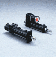
The electromechanicals actuators have been applied to the application following comments and considerations made by our customers.
- Easy to mount
- Reduced dimensions
- Minimum maintenance costs
- Competitive price
|
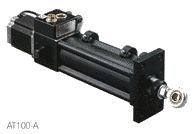
All the linear actuators are operated by stepping motors, which are connected to the actuator by a gearbox, which increases the torque.
The Series AT actuators are available in several configurations and are able to develop a thrust force of 500 Kg at a maximum speed of 40 mm per second, that can be modified by the panel MWG.52.
To ensure that an efficient and precise guide of the material is made, it is important that the correct actuator is selected for each application.
As can be seen in figure for the unwind guide the mechanical structure of the unwind machine must move behind the guide roll, so as to guarantee a good friction on the material.
The sensor must be positioned and fixed immediately after the guide roll.
For unwind applications the sensor must move with all the winding structure. It is also necessary to have a fixed roll guide between the sensor and the winding machine with the contact edge of at least 15 to 20 degrees.
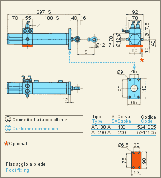
Actuators are available with 2 mounting options, flange or base styles.
|
Technical characteristic and dimensions - AT100-A - AT200-A
|
| |

|

|
|
Technical characteristic and dimensions - AT100-R - AT200-R
|
| |
|
|
|
|

|
 |
| |
Pivot frame Series WG |
| |
|
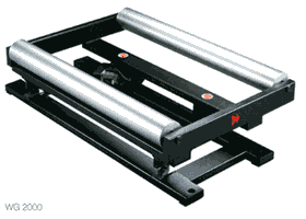
The guide system with pivoting frame, Series WG, has been designed to make the correction of bands of material while occupying the minimum of space.
The guide system Series WG is commonly used with two parallel rolls and must be positioned as near as possible to the zone were maximum guide precision is to be obtained. It is important that in the position of servo centre the rolls are perfectly parallel to the rest of the machine. The sensor must be located as near as possible to the output guide roll.
The input (E) and the output (U) spaces must usually be bigger than half the width of the band.
In order to facilitate its position on the machine, the WG web guide system allows you 4 different runs for a total of 16 mounting position.
The pivot frame Series WG are controlled by a linear actuator, driven by a stepping motor.
The guide rollers are aluminium as standard, but can be rubber or cork coated or anodised as options.?
As the sensor must be positioned close to the guide roll, we advise using our web path, so that the sensor can then be fixed directly on the web guide frame.
The WG carriers can be supplied as a complete assembly, housed in a metal framework, along with the input and output correction rolls. The MWG.52 control can also be housed in the framework, giving a very compact unit which is electronically calibrated at our factory, reducing the chance of installation problems. |
Technical characteristic and dimensions - WG 250 |
| |
|
|
| |
| |
Technical characteristic and dimensions - WG 700 |
|
|
|
| |
| |
Technical characteristic and dimensions - WG 2000 |
| |
|
 |
|

|
 |
| |
Steering rolls Series WR |
| |
|
|
The system with steering rolls Series WR has the characteristic of having movement of the rolls either lateral or angular.
The movement centers around an ideal position of rotation, situated at the beginning of the input space. For this reason the input space (L) must be of enough length to ensure the correction of the band. |
Technical characteristic and dimensions - WR without base |
| |
|
|
| |
Technical characteristic and dimensions - WR with base
|
| |
|
|
|
|
|
|
 |
|
|

